In This article I’ll discuss about configuration of Link aggregation protocol between Fortigate Firewall and Cisco Switch.
Here’s the topology used :
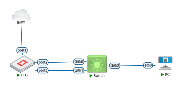
On the topology above, I’ll use two links toward the Cisco switch and then configure a VLAN to PC connection.
Configure Interface LAG on Fortigate First.
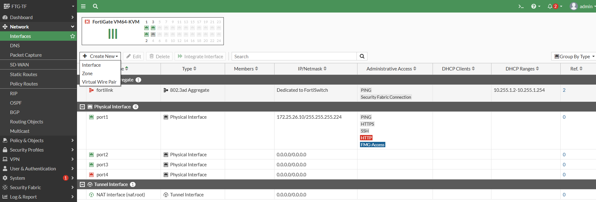
Select on Network > Interface > Create New > Interface
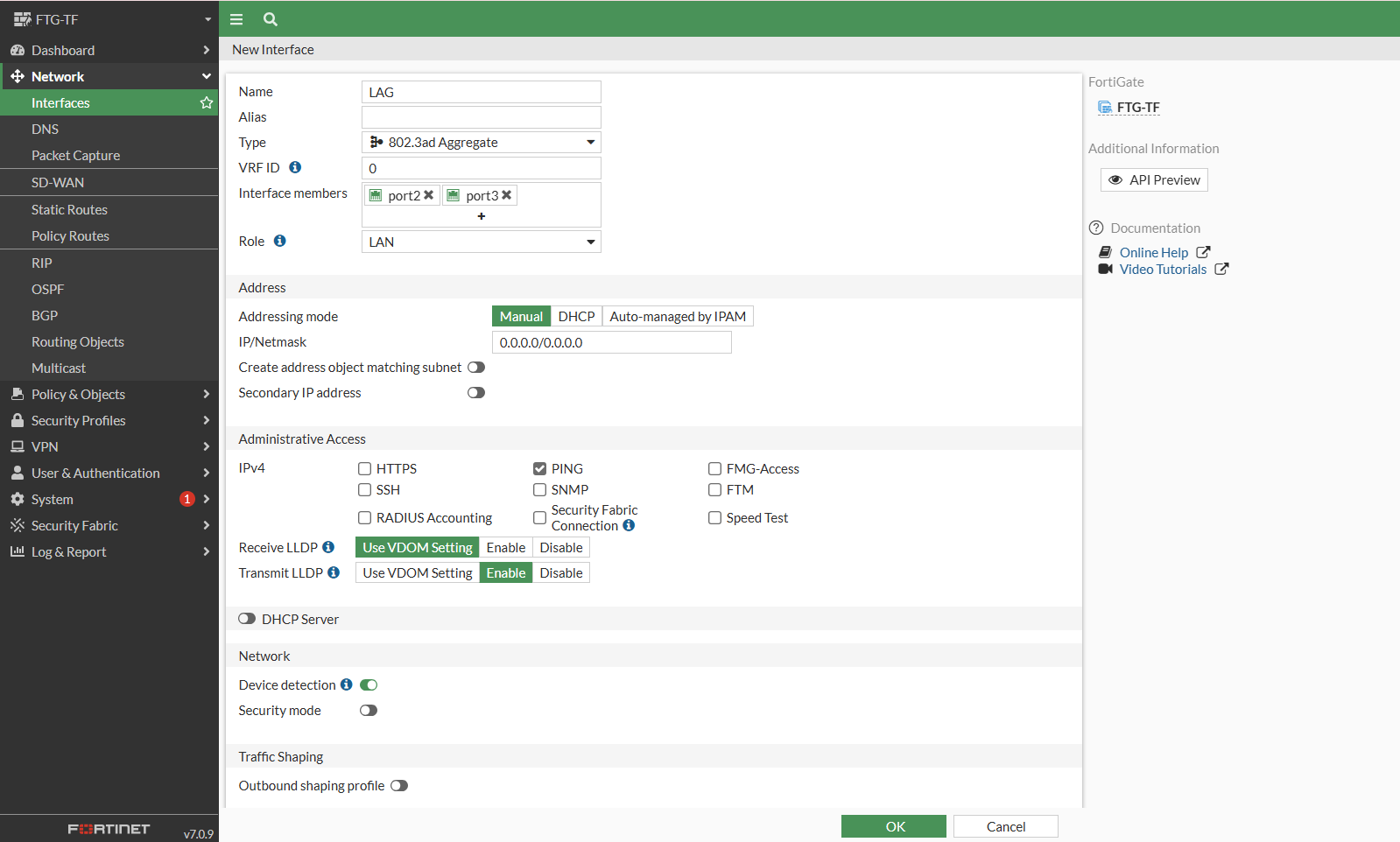
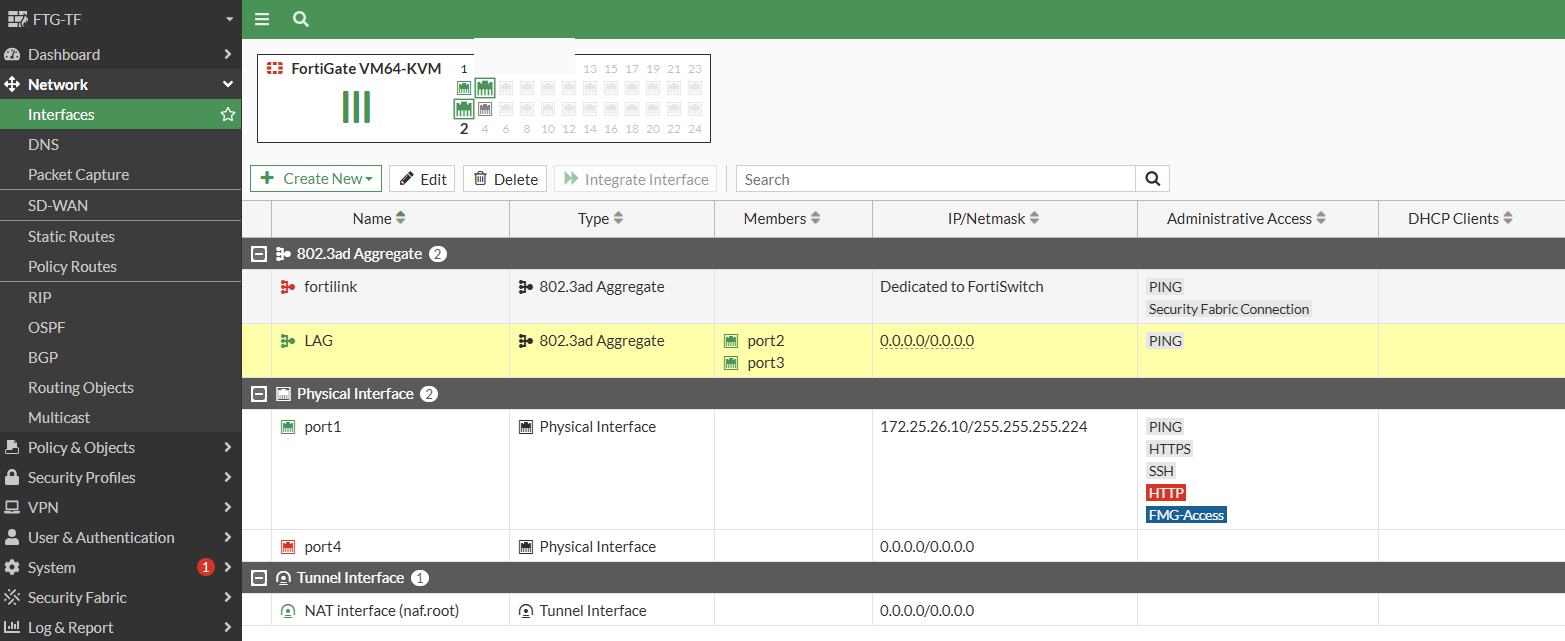
Enter the Interface name, Selct type with 802.3ad Aggregate. Then Select the Interface members with Port2 and Port3.
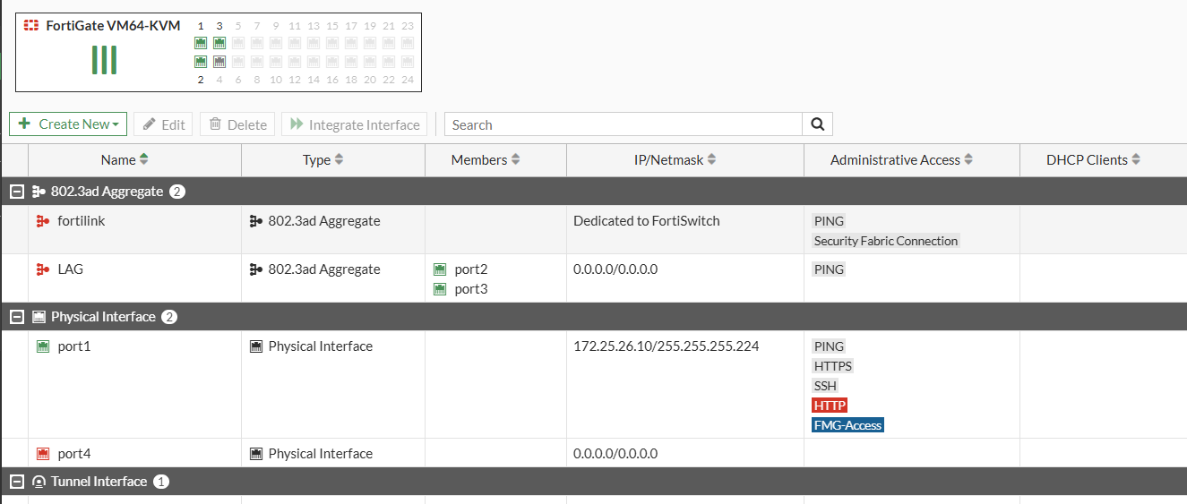
As shown below, the LAG interface has been created, but still not up yet. That’s because the LAG interface on the Cisco switch is has not been configured yet.
Now Let’s configure on the Cisco Switch side. Configure the Etherchannel with LACP Mode.
Switch(config)#int range g0/0-1
Switch(config-if-range)#channel-group 1 mode active
Creating a port-channel interface Port-channel 1
Switch(config-if-range)#
Then Configure Port channel as trunk port.
Switch(config)#int po1
Switch(config-if)#no shut
Switch(config-if)#switchport trunk encapsulation dot1q
Switch(config-if)#switchport mode trunk
Switch(config-if)#
*Jun 15 04:29:15.870: %LINK-3-UPDOWN: Interface Port-channel1, changed state to down
*Jun 15 04:29:16.870: %LINEPROTO-5-UPDOWN: Line protocol on Interface Port-channel1, changed state to down
*Jun 15 04:29:22.556: %LINK-3-UPDOWN: Interface Port-channel1, changed state to up
*Jun 15 04:29:23.556: %LINEPROTO-5-UPDOWN: Line protocol on Interface Port-channel1, changed state to up
Switch(config-if)#
Next, Verify the LAG interface status on the Fortigate and Cisco Switch.
As shown below, you can see the LAG interface on Fortigate is now UP.
And the LAG on the Cisco Switch is also UP.
Switch#show etherchannel summary
Flags: D - down P - bundled in port-channel
I - stand-alone s - suspended
H - Hot-standby (LACP only)
R - Layer3 S - Layer2
U - in use N - not in use, no aggregation
f - failed to allocate aggregator

M - not in use, minimum links not met
m - not in use, port not aggregated due to minimum links not met
u - unsuitable for bundling
w - waiting to be aggregated
d - default port

A - formed by Auto LAG


Number of channel-groups in use: 1
Number of aggregators: 1

Group Port-channel Protocol Ports
------+-------------+-----------+-----------------------------------------------
1 Po1(SU) LACP Gi0/0(P) Gi0/1(P)

Switch#
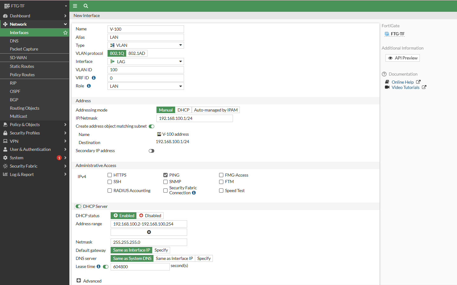
After that configure VLAN 100 on the Fortigate LAG Interface. I’ll enable DHCP Server to provide IP Addresses to connected PCs.
On the Cisco Switch Side configure vlan 100 and assign the PC-connected port as an access port in vlan 100.
Switch(config)#vlan 100
Switch(config-vlan)#exit
Switch(config)#int g0/2
Switch(config-if)#switchport mode access
Switch(config-if)#switchport access vlan 100
Switch(config-if)#end
Switch#
Then configure the DHCP on the PCs and perform a Ping test to the Gateway IP, which is the Vlan 100 fortigate ip.
PC> ip dhcp
DDORA IP 192.168.100.2/24 GW 192.168.100.1

PC> ping 192.168.100.1

84 bytes from 192.168.100.1 icmp_seq=1 ttl=255 time=1.912 ms
84 bytes from 192.168.100.1 icmp_seq=2 ttl=255 time=2.582 ms
84 bytes from 192.168.100.1 icmp_seq=3 ttl=255 time=2.650 ms
84 bytes from 192.168.100.1 icmp_seq=4 ttl=255 time=2.335 ms
84 bytes from 192.168.100.1 icmp_seq=5 ttl=255 time=3.041 ms

PC>
As the shown above, the LAG configuration between fortigate firewall and Cisco switch is successfull.