802.1Q tunneling (Q-in-Q) is a services that creates Layer 2 Tunneling by adding second vlan tag on the Ethernet Frames. is often used by Metro Ethernet Service Provider to tunnel traffic between their customers. I Think is called VLAN running in the VLAN.
As the example topology below we can see that we have two Connection sites with the different location. But we have requirement to keep connecting both as layer vlan connection.
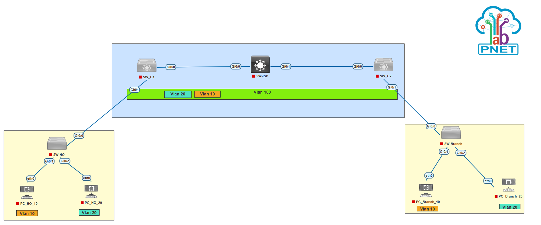 Now Let’s start configuration from SW-ISP, SW_C1 and SW_C2.
Configuration on SW-ISP, Create VLAN 100 and configuration trunk on interface g0/0-1
SW-ISP(config)#vlan 100
SW-ISP(config-vlan)#name QinQ-Tunneling
SW-ISP(config-vlan)#exit
SW-ISP(config)#int range g0/0-1
SW-ISP(config-if-range)#switchport trunk encapsulation dot1q
SW-ISP(config-if-range)#switchport mode trunk
SW-ISP(config-if-range)#end
Configuration on SW_C1
Create VLAN 100
SW_C1(config)#vlan 100
SW_C1(config-vlan)#name QinQ-Tunneling
SW_C1(config-vlan)#exit
Config interface trunk on G0/0 interface
SW_C1(config)#int g0/0
SW_C1(config-if)#switchport trunk encapsulation dot1q
SW_C1(config-if)#switchport mode trunk
SW_C1(config-if)#switchport trunk allowed vlan 100
SW_C1(config-if)#end
SW_C1#
Configure QinQ Tunneling on G0/1. which is the interface connected to the customer.
SW_C1(config)#int g0/1
SW_C1(config-if)#switchport mode dot1q-tunnel
SW_C1(config-if)#l2protocol-tunnel
SW_C1(config-if)#switchport access vlan 100
SW_C1(config-if)#exit
SW_C1(config)#
Configuration on SW_C2
Create VLAN 100
SW_C2(config)#vlan 100
SW_C2(config-vlan)#name QinQ-Tunneling
SW_C2(config-vlan)#exit
Config interface trunk on G0/0 interface
SW_C2(config)#int g0/0
SW_C2(config-if)#switchport trunk encapsulation dot1q
SW_C2(config-if)#switchport mode trunk
SW_C2(config-if)#switchport trunk allowed vlan 100
SW_C2(config-if)#exit
Configure QinQ Tunneling on G0/1. which is the interface connected to the customer.
SW_C2(config)#int g0/1
SW_C2(config-if)#switchport mode dot1q-tunnel
SW_C2(config-if)#l2protocol-tunnel
SW_C2(config-if)#switchport access vlan 100
SW_C2(config-if)#end
SW_C2#
Now Configure SW-HO and Branch
Configure SW-HO
Add Vlan 10 and Vlan 20
SW-HO(config)#vlan 10
SW-HO(config-vlan)#exit
SW-HO(config)#vlan 20
SW-HO(config-vlan)#exit
Configure switch port trunk on G0/0 that connected to SW_C1
SW-HO(config)#int g0/0
SW-HO(config-if)#switchport trunk encapsulation dot1q
SW-HO(config-if)#switchport mode trunk
SW-HO(config-if)#exit
Then Configure access port to PC
SW-HO(config)#int g0/1
SW-HO(config-if)#switchport mode access
SW-HO(config-if)#switchport access vlan 10
SW-HO(config-if)#exit
SW-HO(config)#int g0/2
SW-HO(config-if)#switchport mode access
SW-HO(config-if)#switchport access vlan 20
SW-HO(config-if)#exit
SW-HO(config)#
Configure SW-Branch
Add Vlan 10 and Vlan 20
SW-Branch(config)#vlan 10
SW-Branch(config-vlan)#exit
SW-Branch(config)#vlan 20
SW-Branch(config-vlan)#exit
Configure switch port trunk on G0/0 that connected to SW_C2
SW-Branch(config)#int g0/0
SW-Branch(config-if)#switchport trunk encapsulation dot1q
SW-Branch(config-if)#switchport mode trunk
SW-Branch(config-if)#exit
Then Configure access port to PC
SW-Branch(config)#int g0/1
SW-Branch(config-if)#switchport mode access
SW-Branch(config-if)#switchport access vlan 10
SW-Branch(config-if)#exit
SW-Branch(config)#int g0/2
SW-Branch(config-if)#switchport mode access
SW-Branch(config-if)#switchport access vlan 20
SW-Branch(config-if)#exit
SW-Branch(config)#
Configure ip address on PCHO10
PCHO10> ip 192.168.10.1/24
Checking for duplicate address...
PC1 : 192.168.10.1 255.255.255.0
PCHO10>
Configure ip address on PCHO20
PCHO20> ip 192.168.20.1/24
Checking for duplicate address...
PC1 : 192.168.20.1 255.255.255.0
PCHO20>
Config ip address on PCBR10
PCBR10> ip 192.168.10.2/24
Checking for duplicate address...
PC1 : 192.168.10.2 255.255.255.0
PCBR10>
Config ip address on PCBR20
PCBR20> ip 192.168.20.2/24
Checking for duplicate address...
PC1 : 192.168.20.2 255.255.255.0
PCBR20>
After that do a ping test between PCs HO and Branch.
PCHO10> ping 192.168.10.2
84 bytes from 192.168.10.2 icmp_seq=1 ttl=64 time=42.641 ms
84 bytes from 192.168.10.2 icmp_seq=2 ttl=64 time=19.437 ms
84 bytes from 192.168.10.2 icmp_seq=3 ttl=64 time=20.863 ms
84 bytes from 192.168.10.2 icmp_seq=4 ttl=64 time=18.621 ms
84 bytes from 192.168.10.2 icmp_seq=5 ttl=64 time=27.816 ms
PCHO10>
PCHO20> ping 192.168.20.2
84 bytes from 192.168.20.2 icmp_seq=1 ttl=64 time=14.547 ms
84 bytes from 192.168.20.2 icmp_seq=2 ttl=64 time=15.672 ms
84 bytes from 192.168.20.2 icmp_seq=3 ttl=64 time=19.206 ms
84 bytes from 192.168.20.2 icmp_seq=4 ttl=64 time=40.554 ms
84 bytes from 192.168.20.2 icmp_seq=5 ttl=64 time=27.468 ms
PCHO20>
PCBR10> ping 192.168.10.1
84 bytes from 192.168.10.1 icmp_seq=1 ttl=64 time=17.805 ms
84 bytes from 192.168.10.1 icmp_seq=2 ttl=64 time=22.574 ms
84 bytes from 192.168.10.1 icmp_seq=3 ttl=64 time=14.186 ms
84 bytes from 192.168.10.1 icmp_seq=4 ttl=64 time=43.997 ms
84 bytes from 192.168.10.1 icmp_seq=5 ttl=64 time=18.362 ms
PCBR10>
PCBR20> ping 192.168.20.1
84 bytes from 192.168.20.1 icmp_seq=1 ttl=64 time=17.707 ms
84 bytes from 192.168.20.1 icmp_seq=2 ttl=64 time=22.481 ms
84 bytes from 192.168.20.1 icmp_seq=3 ttl=64 time=15.062 ms
84 bytes from 192.168.20.1 icmp_seq=4 ttl=64 time=26.976 ms
84 bytes from 192.168.20.1 icmp_seq=5 ttl=64 time=15.206 ms
PCBR20>
As you can see above, the connection between PC HO and Branch that connected on VLAN10 and VLAN20 is successfull.
Now verify cdp neighbor on SW-HO and Branch.
SW-HO#show cdp nei
Capability Codes: R - Router, T - Trans Bridge, B - Source Route Bridge
S - Switch, H - Host, I - IGMP, r - Repeater, P - Phone,
D - Remote, C - CVTA, M - Two-port Mac Relay

Device ID Local Intrfce Holdtme Capability Platform Port ID
SW-Branch Gig 0/0 140 R S I Gig 0/0

Total cdp entries displayed : 1
SW-HO#
SW-Branch#show cdp nei
Capability Codes: R - Router, T - Trans Bridge, B - Source Route Bridge
S - Switch, H - Host, I - IGMP, r - Repeater, P - Phone,
D - Remote, C - CVTA, M - Two-port Mac Relay

Device ID Local Intrfce Holdtme Capability Platform Port ID
SW-HO Gig 0/0 146 R S I Gig 0/0

Total cdp entries displayed : 1
SW-Branch#
As you can see above, CDP neighboor on SW-HO is a SW Branch. also CDP Neighboor on SW-Branch is SW-HO. That’s like both switch are directly connected while in real topology is connected to another switch.