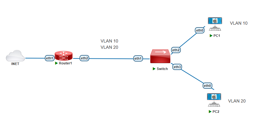
Hello everyone, in this tutorial I’ll discuss about configuration VLAN Management on Mikrotik. Refers to the Topology Below, I have 2 Mikrotik devices that act as Router and Switch that running two VLANs.
First step don’t forget to do a basic configuration on Router1 so that the Router internet access and provide an internet connection for PCs.
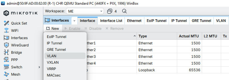
Then Create a VLAN interfaces on Router1
- Select Interfaces > New > VLAN
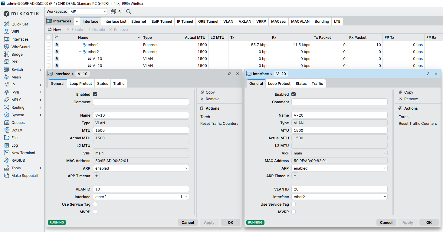
Create Two VLAN interface which is VLAN 10 and VLAN 20
- Name : is optional to vlan name
- VLAN ID : VlanID for vlan interface (10 & 20)
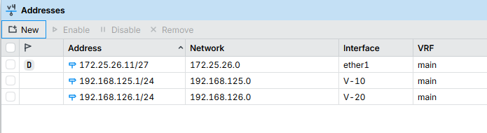
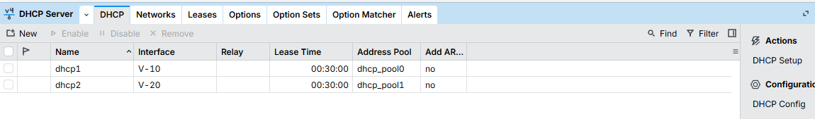
Configure IP Address and IP DHCP Servers for VLAN 10 and VLAN 20 interfaces to provide dhcp service for the PCs. Refers to Configure DHCP Mikrotik to DHCP Configuration.
Then Configure on the Switch.
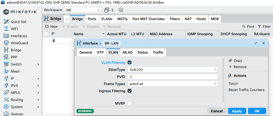
Configure Bridge Interface
- Select Bridge > Bridge > New
- On General Tab input name : BR-LAN (optional)
- Move to VLAN tab > Enable VLAN Filtering
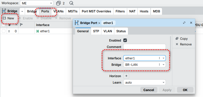
After Create Bridge Interface, Select Ports tab.
- Create New Add interface ether1 with Bridge BR-LAN. Ether1 is used to tagged port to Router1
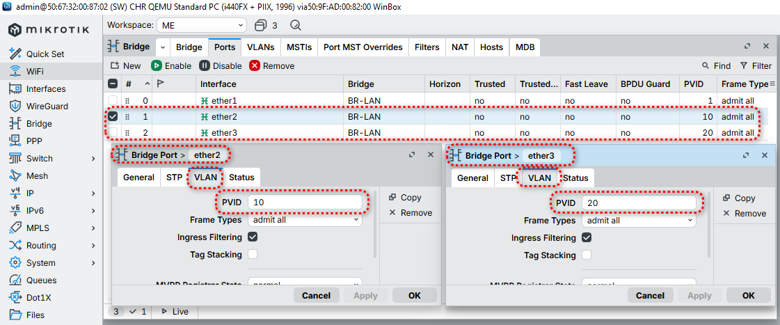
Add new port for Interface ether2 and ether3 for VLAN10 and VLAN20 connection.
- On General tab Configure for Interface (ether2 and ether3 each) with Bridge interface BR-LAN.
- Then move to VLAN tab
- add PVID : 10 (for ether2 with vlan10 connection)
- add PVID : 20 (for ether3 with vlan20 connection)
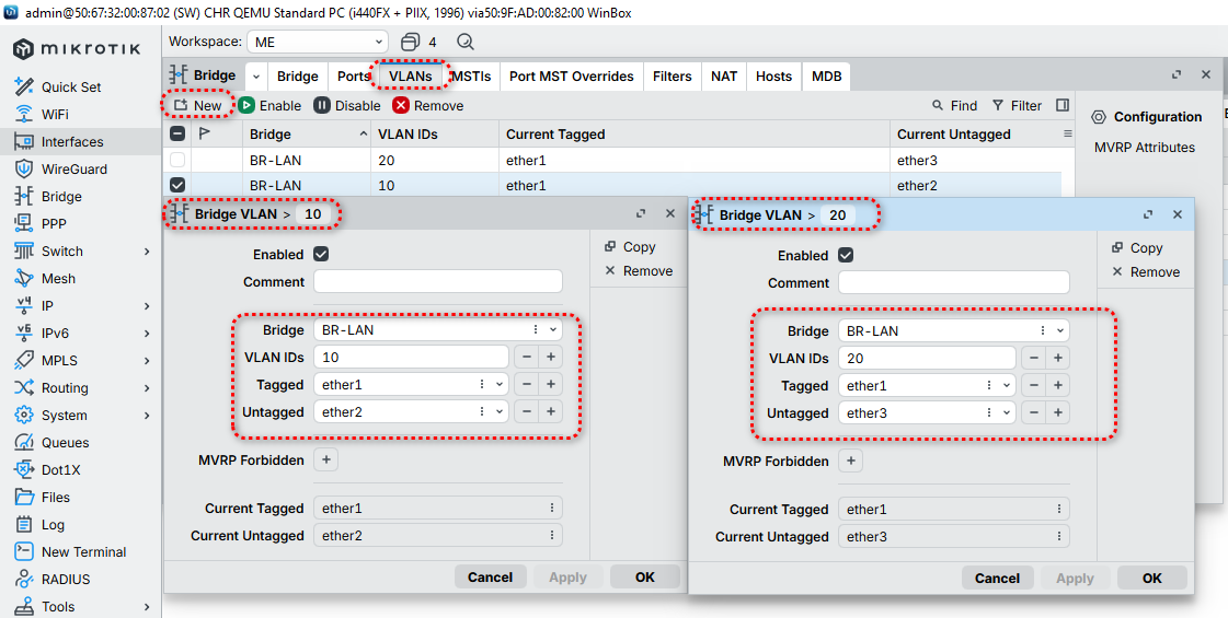
After that move to VLANs tab
- Configure tagging and untagging ports. Select New
- Bridge VLAN 10
- Bridge : BR-LAN
- VLAN IDs : 10
- Tagged : ether1
- Untagged : ether2
- Bridge VLAN 20
- Bridge : BR-LAN
- VLAN IDs : 20
- Tagged : ether1
- Untagged : ether3
Now Testing on PCs.
Configure ip dhcp on PC1. as shown below PC1 is success to get ip dhcp from VLAN10.
PC1> ip dhcp
DORA IP 192.168.125.50/24 GW 192.168.125.1
PC1>
Configure ip dhcp on PC2. as shown below PC2 is success to get ip dhcp from VLAN20.
PC2> ip dhcp
DORA IP 192.168.126.50/24 GW 192.168.126.1
PC2>
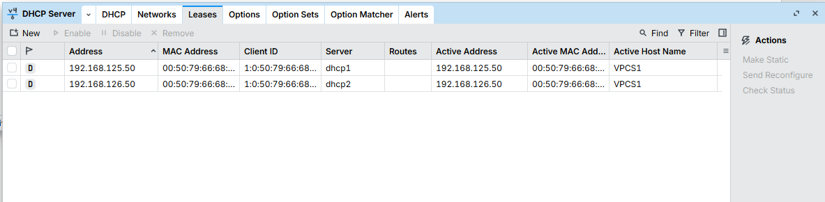
Monitor on Router1 DHCP leases :
Connection test for PC1 and PC2
PC1> ping 8.8.8.8
84 bytes from 8.8.8.8 icmp_seq=1 ttl=114 time=20.147 ms
84 bytes from 8.8.8.8 icmp_seq=2 ttl=114 time=21.311 ms
84 bytes from 8.8.8.8 icmp_seq=3 ttl=114 time=21.922 ms
84 bytes from 8.8.8.8 icmp_seq=4 ttl=114 time=22.129 ms
84 bytes from 8.8.8.8 icmp_seq=5 ttl=114 time=21.052 ms
PC1> trace 8.8.8.8
trace to 8.8.8.8, 8 hops max, press Ctrl+C to stop
1 192.168.125.1 1.249 ms 1.169 ms 1.376 ms
......................
4 8.8.8.8 2.687 ms 4.192 ms 4.537 ms
PC1>
PC2> ping 8.8.8.8
84 bytes from 8.8.8.8 icmp_seq=1 ttl=114 time=21.277 ms
84 bytes from 8.8.8.8 icmp_seq=2 ttl=114 time=20.637 ms
84 bytes from 8.8.8.8 icmp_seq=3 ttl=114 time=20.360 ms
84 bytes from 8.8.8.8 icmp_seq=4 ttl=114 time=22.292 ms
84 bytes from 8.8.8.8 icmp_seq=5 ttl=114 time=21.259 ms
PC2> trace 8.8.8.8
trace to 8.8.8.8, 8 hops max, press Ctrl+C to stop
1 192.168.126.1 1.259 ms 1.009 ms 0.958 ms
......................
4 8.8.8.8 12.182 ms 5.216 ms 3.330 ms
PC2>