After In Previous article we have discuss about OSPF DR & BDR Concept, Now I’ll discuss about configuration OSPF DR and BDR on Cisco.
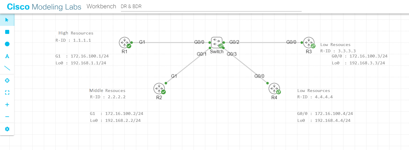
The Following is topology :

We have four routers which running OSPF routing protocol and where the routers have different resources. R1 has high resources, R2 with middle resources, R3 & R4 have low resources. But based on the topology concept, R4 and R3 that have low resources will become DR and BDR.
To Deep dive about the concept, Let’s configure the ospf on each router first.
IP Address Configuration :
R1(config)#int g1
R1(config-if)#ip add 172.16.100.1 255.255.255.0
R1(config-if)#no shut
R1(config-if)#exit
R1(config-if)#
R1(config-if)#ip add 192.168.1.1 255.255.255.0
R1(config-if)#exit
R1(config)#
R2(config)#int g1
R2(config-if)#ip add 172.16.100.2 255.255.255.0
R2(config-if)#no shut
R2(config-if)#exit
R2(config)#int lo0
R2(config-if)#ip add 192.168.2.2 255.255.255.0
R2(config-if)#exit
R2(config)#
R3(config)#int g0/0
R3(config-if)#ip add 172.16.100.3 255.255.255.0
R3(config-if)#no shut
R3(config-if)#exit
R3(config)#int lo0
R3(config-if)#ip add
R3(config-if)#exit
R3(config)#
R4(config)#int g0/0
R4(config-if)#ip add 172.16.100.4 255.255.255.0
R4(config-if)#no shut
R4(config-if)#exit
R4(config)#int lo0
R4(config-if)#ip add 192.168.4.4 255.255.255.0
R4(config-if)#exit
R4(config)#
OSPF Configuration :
R1(config)#router ospf 1
R1(config-router)#router-id 1.1.1.1
R1(config-router)#network 172.16.100.0 0.0.0.255 area 0
R1(config-router)#network 192.168.1.0 0.0.0.255 area 0
R1(config-router)#exit
R1(config)#
R2(config)#router ospf 1
R2(config-router)#router-id
R2(config-router)#router-id 2.2.2.2
R2(config-router)#network 172.16.100.0 0.0.0.255 area 0
R2(config-router)#network 192.168.2.0 0.0.0.255 area 0
R2(config-router)#exit
R2(config)#
R3(config)#router ospf 1
R3(config-router)#router-id 3.3.3.3
R3(config-router)#network 172.16.100.0 0.0.0.255 area 0
R3(config-router)#network 192.168.3.0 0.0.0.255 area 0
R3(config-router)#exit
R3(config)#
R4(config)#router ospf 1
R4(config-router)#router-id 4.4.4.4
R4(config-router)#network 172.16.100.0 0.0.0.255 area 0
R4(config-router)#network 192.168.4.0 0.0.0.255 area 0
R4(config-router)#exit
R4(config)#
After complete the configuration, Let’s check the ip neighbor on each routers.
OSPF Neighbor on R1.
R1#show ip ospf nei

Neighbor ID     Pri     State          Dead Time    Address        Interface
2.2.2.2           1     2WAY/DROTHER   00:00:34     172.16.100.2   GigabitEthernet1
3.3.3.3           1     FULL/BDR       00:00:35     172.16.100.3   GigabitEthernet1
4.4.4.4           1     FULL/DR        00:00:34     172.16.100.4   GigabitEthernet1
R1#
OSPF Neighbor on R2.
R2#show ip ospf neiNeighbor ID Pri State Dead Time Address Interface 1.1.1.1 1 2WAY/DROTHER 00:00:38 172.16.100.1 GigabitEthernet1 3.3.3.3 1 FULL/BDR 00:00:34 172.16.100.3 GigabitEthernet1 4.4.4.4 1 FULL/DR 00:00:34 172.16.100.4 GigabitEthernet1 R2#
OSPF Neighbor on R3.
R3#show ip ospf nei

Neighbor ID    Pri   State          Dead Time    Address         Interface
1.1.1.1          1   FULL/DROTHER   00:00:34     172.16.100.1    GigabitEthernet0/0
2.2.2.2          1   FULL/DROTHER   00:00:30     172.16.100.2    GigabitEthernet0/0
4.4.4.4          1   FULL/DR        00:00:30     172.16.100.4    GigabitEthernet0/0
R3#
OSPF Neighbor on R4.
R4#show ip ospf nei

Neighbor ID   Pri    State          Dead Time    Address         Interface
1.1.1.1         1    FULL/DROTHER   00:00:37     172.16.100.1    GigabitEthernet0/0
2.2.2.2         1    FULL/DROTHER   00:00:33     172.16.100.2    GigabitEthernet0/0
3.3.3.3         1    FULL/BDR       00:00:32     172.16.100.3    GigabitEthernet0/0
R4#
As the shown above, you can see there are 3 neighbor on each routers. Pay attention to the State because every neighbor router has different state (2WAY/DROTHER, FULL/DROTHER, FULL/DR and FULL/BDR).
Let’s start from R1. The R1 to the R2 neighbor has 2WAY/DROTHER state, That’s mean the R2 is not a DR or BDR. Also on R2 , the neighbor state to the R1 is 2WAY/DROTHER that’s mean the R1 also not the DR or BDR. Then see for the neighbor to R3 and R4, you can see the R4 is become DR and R3 become BDR.
The conclution is on the OSPF, routers will only do a FULL state adjacency and routing information exchanges with DR and BDR. Then between routers DR and BDR will be communicate to sync OSPF database.
Based on the result above, it’s not recomended result because routers that’s become DR & BDR is a router with low resources and it’s will impact the router resource exhaustion. To solved that issue we will modify or Manipulation ospf priority.
Configure ospf interface priority on R1 with highest priority so that these router will become DR.
R1(config)#int g1
R1(config-if)#ip ospf priority 5
R1(config-if)#exit
R1(config)#
Then Configure ospf interface priorty on R2 with 2nd highest priority so that these router will become BDR.
R2(config)#int g1
R2(config-if)#ip ospf pri
R2(config-if)#ip ospf priority 3
R2(config-if)#exit
After that clear ke ospf proccess on all routers with clear ip ospf process command.
# clear ip ospf proccess
Now show the ospf neighbor again and see the result.
R1#show ip ospf neighbor

Neighbor ID   Pri     State          Dead Time    Address         Interface
2.2.2.2         3     FULL/BDR       00:00:39     172.16.100.2    GigabitEthernet1
3.3.3.3         1     FULL/DROTHER   00:00:35     172.16.100.3    GigabitEthernet1
4.4.4.4         1     FULL/DROTHER   00:00:34     172.16.100.4    GigabitEthernet1
R1#
R2#show ip ospf nei

Neighbor ID  Pri     State           Dead Time    Address         Interface
1.1.1.1        5     FULL/DR         00:00:39     172.16.100.1    GigabitEthernet1
3.3.3.3        1     FULL/DROTHER    00:00:35     172.16.100.3    GigabitEthernet1
4.4.4.4        1     FULL/DROTHER    00:00:34     172.16.100.4    GigabitEthernet1
R2#
R3#show ip ospf neighbor

Neighbor ID   Pri    State          Dead Time     Address         Interface
1.1.1.1         5    FULL/DR        00:00:33      172.16.100.1    GigabitEthernet0/0
2.2.2.2         3    FULL/BDR       00:00:32      172.16.100.2    GigabitEthernet0/0
4.4.4.4         1    2WAY/DROTHER   00:00:39      172.16.100.4    GigabitEthernet0/0
R3#
R4#show ip ospf neighbor

Neighbor ID   Pri   State          Dead Time      Address         Interface
1.1.1.1         5   FULL/DR        00:00:39       172.16.100.1    GigabitEthernet0/0
2.2.2.2         3   FULL/BDR       00:00:38       172.16.100.2    GigabitEthernet0/0
3.3.3.3         1   2WAY/DROTHER   00:00:35       172.16.100.3    GigabitEthernet0/0
R4#
As the shown above you can see the Routers R1 and R2 that has become DR and BDR. DR & BDR Manipulation is successfull.